


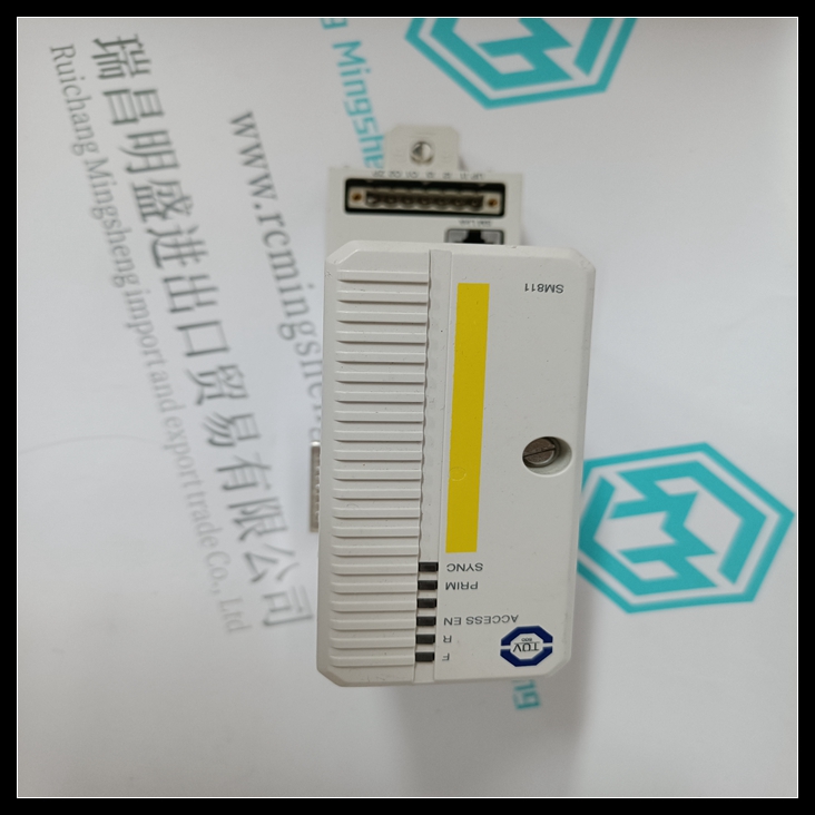
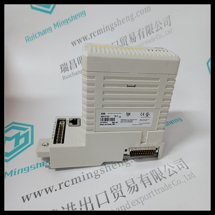
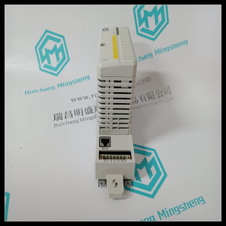
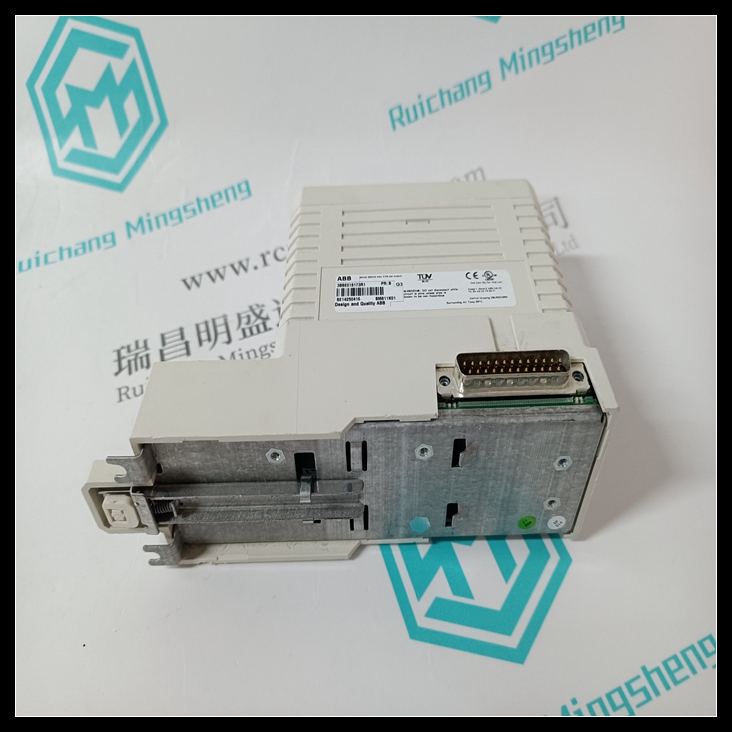
3BSE018173R1处理器模块,3BSE018173R1控制系统
所有现场控制接线板必须安装在35mm x 7.5mm DIN导轨上。
导轨必须具有导电(未涂漆)表面,以便正确接地。
使用多个轨道段时,确保它们正确对齐。SM811K01 3BSE018173R1使DIN导轨至少居中
距离输入/输出接线侧的任何电线槽或其他障碍物4.25英寸(10.80厘米)
")
接线板。如果输入/输出模块的接线非常僵硬,请留出更多空间。
为了增加抗振性,应使用间隔螺钉将DIN导轨安装在面板上
相距约6英寸(5.24cm)。为获得最大的抗振性,所有
接线板安装耳。3BSE018173R1处理器模块输入/输出接线板和辅助接线板的位置
安装耳如右图所示。
将接线板安装到DIN导轨上后,安装3/8英寸(9.525mm)#6个螺钉(非
提供)通过安装耳。
All Field Control Terminal Blocks must be mounted on a 35mm x 7.5mm DIN rail.
The rail must have a conductive (unpainted) finish for proper grounding.
When using multiple rail sections, be sure they are properly aligned. Center the DIN rail at least
4.25 inches (10.80 cm) from any wireway or other obstruction on the wiring side of the I/O
Terminal Block. Allow more space if the wiring for I/O modules is very stiff.
For added vibration resistance, the DIN rail should be installed on a panel using screws spaced
approximately 6 inches (5.24cm) apart. For maximum vibration resistance, drill holes for all
terminal block mounting ears. Locations for I/O Terminal Block and Auxiliary Terminal Block
mounting ears are shown at right.
After mounting the terminal block on the DIN rail, install 3/8-inch (9.525mm) #6 screws (not
supplied) through the mounting ears.

